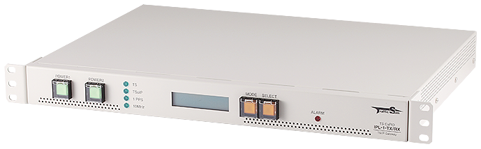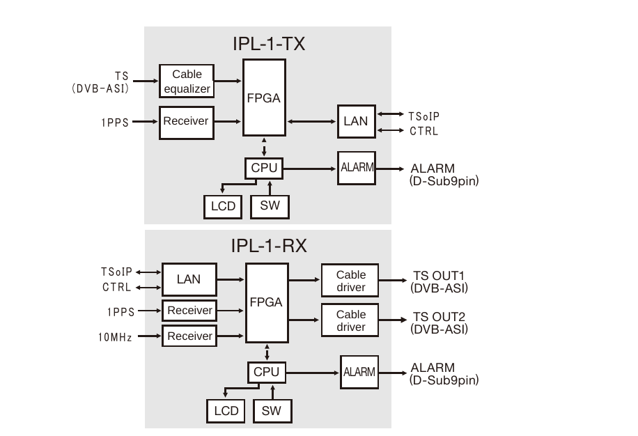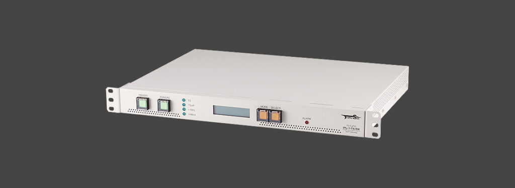
This is a TS-over-IP transmission unit that can be used for building SFN (Single Frequency Network) links for terrestrial digital broadcasting and V-low, as well as backup links for BCP (Business Continuity Planning).
It is operated as a pair consisting of IPL-1-TX and IPL-1-RX.
Features (Delay Control / ARQ / FEC Support)
This unit is equipped with a delay control function that absorbs jitter on IP networks and outputs a stable TS signal with a configured fixed delay.
It can also be used for broadcast TS transmission in SFN environments.
The system operates as a pair consisting of IPL-1-TX and IPL-1-RX.
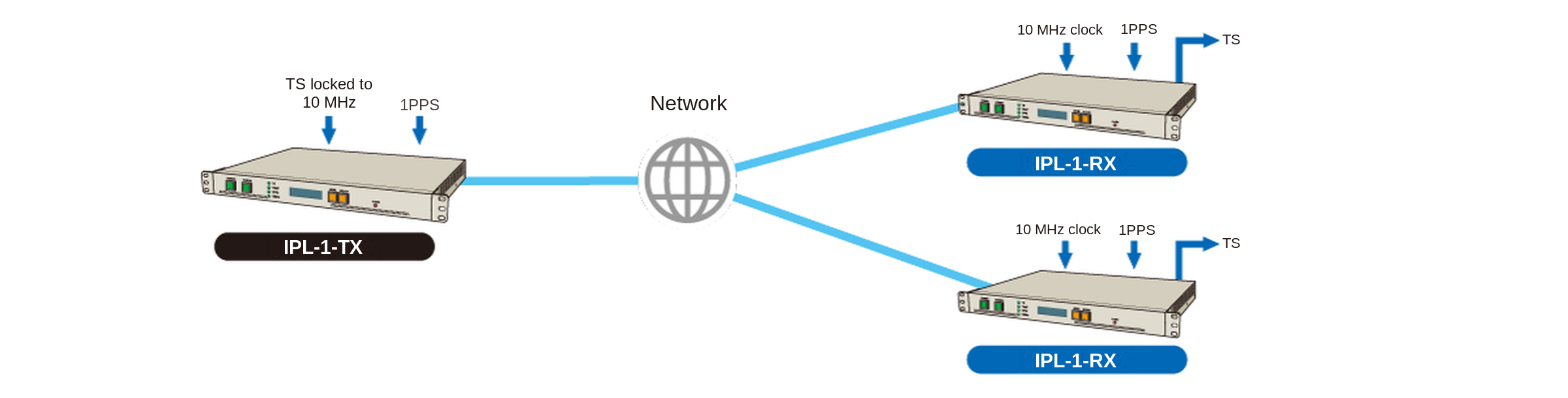
This unit is equipped with a delay control function that absorbs jitter on IP networks and outputs a stable TS signal with a configured fixed delay.
- It can also be used for broadcast TS transmission in SFN environments.
- The system operates as a pair consisting of IPL-1-TX and IPL-1-RX.
Forward Error Correction (FEC) Function
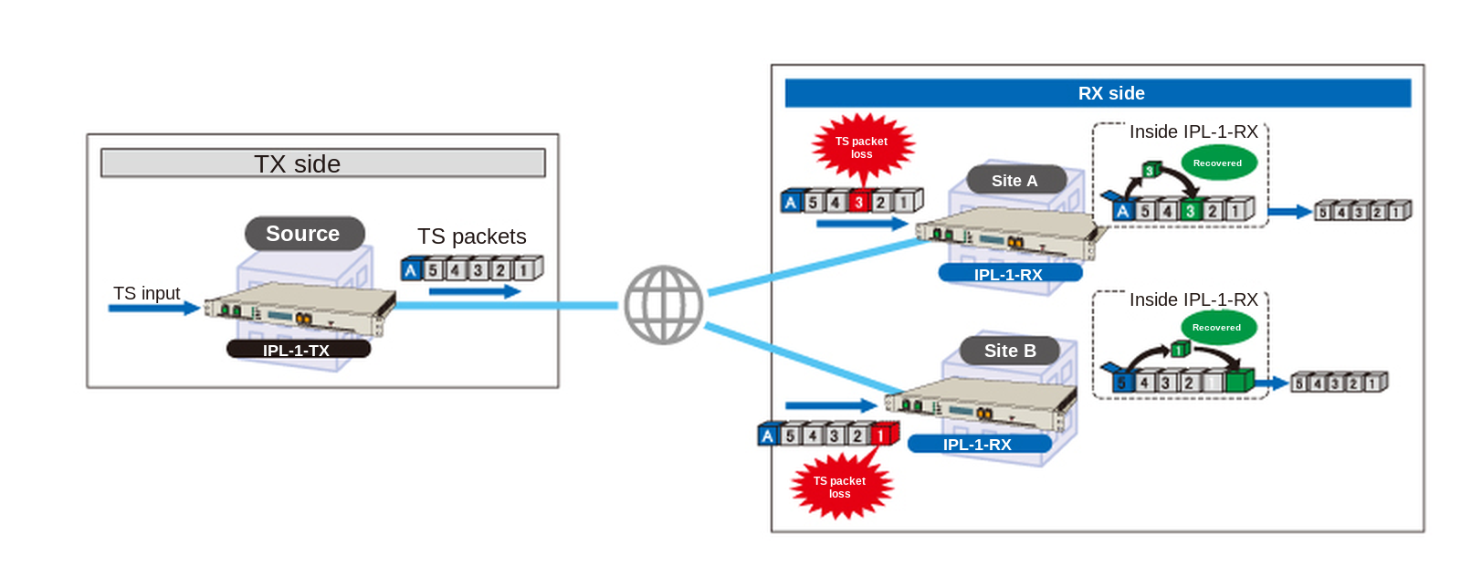
Even if packet loss occurs on the IP network, the missing portions can be compensated for by the proprietary Forward Error Correction (FEC) protocol, allowing continuous operation.
The TS packets to be transmitted are divided into blocks of n × n packets, and n FEC packets are added to each block for transmission.
In a configuration with one transmitter (TX) and multiple receivers (RX), the RX side does not need to request retransmission when IP packet loss occurs, which helps reduce the processing load on the TX side.
Retransmission processing (ARQ) is available in a 1-to-1 configuration.
Delay Function
Synchronous Delay Control
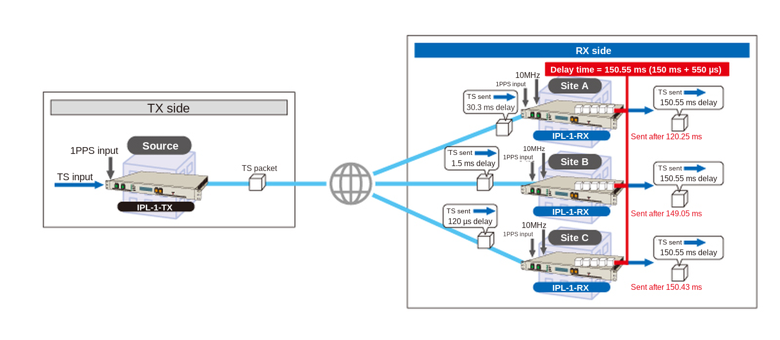
The delay between the TX input TS and RX output TS does not depend on the transmission delay of the IP network.
Instead, it is determined by the Delay time setting on the RX side.
The configurable Delay time range is from [IP transmission delay] to 980 ms (※).
※ The configurable range may become narrower depending on the ARQ/FEC settings and the characteristics of the input TS (NULL packet ratio).
Asynchronous Delay Control
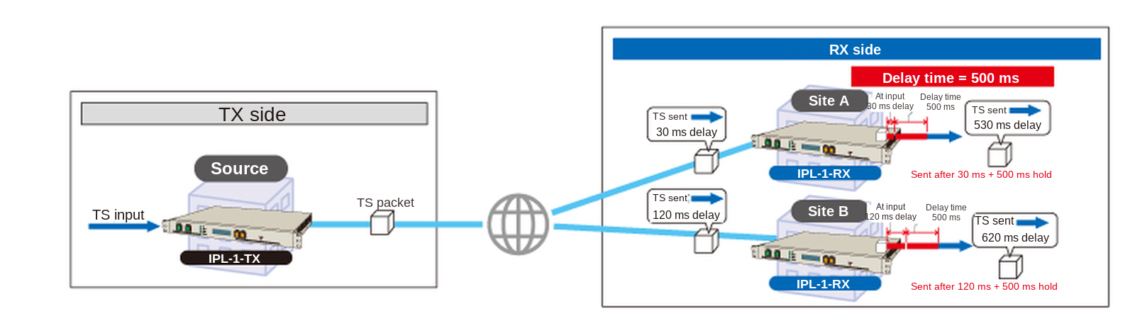
The RX starts output after the configured Delay time has elapsed from the moment it receives the TS packet.
In this case, the delay between the TX input TS and RX output TS becomes the sum of:
IP network transmission delay + Delay time.
The configurable Delay time range is 50 ms to 1500 ms (※).
※ The configurable range may become narrower depending on the ARQ/FEC settings and the characteristics of the input TS (NULL packet ratio).
Specifications
| Product Type | IP Transmission Unit (IPL-1-TX: TS-to-IP converter / IPL-1-RX: IP-to-TS converter) | |
|---|---|---|
| Product Name | TS CaPID IPL-1-TX / RX | |
| Model Number | IPL1TX-A120R-A / IPL1RX-A120R-A | |
| Configuration | IPL-1-TX (transmit side) and IPL-1-RX (receive side) are used as a pair. In addition to one-to-one links, one-to-n (multicast) transmission is supported. (※1) | |
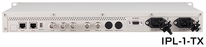
| Input | TS IN | DVB-ASI, BNC 75Ω (※2) Fixed TS bitrate (variable bitrate not supported) Input TS bitrate: up to 33.000 Mbps Used on the IPL-1-TX (not used on the IPL-1-RX) |
| 1PPS IN | TTL level Input impedance: 50Ω Used on both the IPL-1-TX and the IPL-1-RX (※3) | |
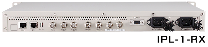
| 10MHz IN | Input allowable range: 0.5–1.0 Vp-p Input impedance: 50Ω Used on the IPL-1-RX (not used on the IPL-1-TX) (※4) | |
| Output | TS OUT 1 / 2 | DVB-ASI (selectable: burst mode / packet mode), BNC 75Ω OUT1 and OUT2 output the same content The IPL-1-RX outputs the transmitted TS; the IPL-1-TX passes the input TS through |
| F-SYNC OUT 1 / 2 | Output impedance: 75Ω Voltage level: 1.0 Vp-p LOW output at the first packet of each broadcast TS frame An option for the IPL-1-RX (not used on the IPL-1-TX) | |
| Interface | TSoIP | RJ-45, 10BASE-T / 100BASE-TX TSoIP packets are carried over UDP (proprietary Traffic Sim protocol format) IGMPv2 supported (when a multicast address is set as the IPL-1-RX receive address) |
| CTRL | RJ-45, 10BASE-T / 100BASE-TX Used for configuration, status retrieval and firmware updates Can be shared with the TSoIP port by configuration | |
| Control I/F | Front: LCD (status and settings), SELECT switch (changes the displayed item) Rear: DIP switch (selects the CTRL port IP address at startup) | |
| Front Indicators (LED) | POWER1 / POWER2: lit green when the power is on (also the power switches; 1 is supply 1, 2 is supply 2) TS: lit green when the IPL-1-TX has a TS input, or when the IPL-1-RX is able to output a TS TSoIP: lit green while the TSoIP port has link 1PPS: lit green while a 1PPS signal is present 10MHz: lit green when the IPL-1-RX has a 10MHz input (unlit on the IPL-1-TX, which does not use it) ALARM: lit red while the contact output has detected a fault | |
| Contact Output | Connector | D-sub 9-pin (female) Inch-thread fixing screws (※5) |
| Monitored Items | TS input / output error TSoIP port connection error 1PPS clock input error 10MHz clock input error (IPL-1-RX only) Power supply 1 error / power supply 2 error Each contact closes while the fault is detected. Pin 5 is the contact GND (common); pins 6 and 7 are not connected (N.C.). | |
| Specifications | MOS FET relay output ・Maximum output voltage: 40V ・Maximum continuous load current: 120mA ・On resistance: typical 1.0–15Ω (max 25Ω) | |
| Delay Settings | When synchronized with 1PPS | 50 ms – 980 ms (※6) |
| When asynchronous | 50 ms – 1500 ms (※6) | |
| Setting resolution | 1 ns | |
| Operating accuracy | ±0.5 μs | |
| Error Correction | Retransmission (ARQ) / Forward Error Correction (FEC) Each can be enabled or disabled (※7) | |
| Power | AC 100–240V, 2 supplies | |
| Power Consumption | 12W, 20VA or less (※8) | |
| Operating Environment | Temperature: 0–40°C Humidity: 30–80% RH (non-condensing) | |
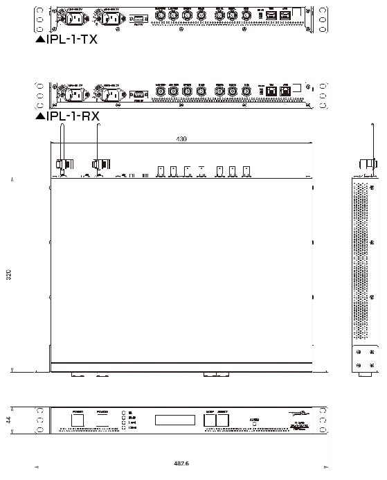
| Dimensions (W × H × D) | EIA 19-inch rack, 1U size 430 × 44 × 320 mm (excluding protrusions) | |
| Weight | Approx. 3.0 kg | |
| Accessories | Dedicated AC100V power cable (※9) User manual | |
| Related Products | MPEG-2 TS → TS over IP Conversion Unit (WA-5-TI) TS over IP → MPEG-2 TS Conversion Unit (WA-5-IT) | |
(※1) For one-to-n operation with more than three IPL-1-RX units, Forward Error Correction (FEC) is recommended instead of retransmission (ARQ). If retransmission requests arrive from many IPL-1-RX units at once, the IPL-1-TX may not be able to keep up.
(※2) DVB-ASI supports burst mode and packet mode.
(※3) To operate in 1PPS synchronized mode, a 1PPS signal whose rising edges are synchronized must be supplied to both the IPL-1-TX and the IPL-1-RX.
(※4) The TS output rate of the IPL-1-RX is (2048/63) Mbps (approx. 32.508 Mbps), synchronized to the applied 10MHz clock.
(※5) Can be changed to metric screws as an option. For metric screws, the model number suffix will be (M).
(※6) The stated ranges are guidelines. The usable range narrows depending on whether retransmission (ARQ) and Forward Error Correction (FEC) are enabled, on the transmission network, and on the proportion of NULL packets in the TS.
(※7) Retransmission (ARQ) is configured on the IPL-1-RX; Forward Error Correction (FEC) is configured on the IPL-1-TX.
(※8) If power supply 1 and power supply 2 are fed from separate sources, make sure each source can supply the required power.
(※9) The supplied dedicated power cable meets the requirements of Japan’s Electrical Appliance and Material Safety Act. Always use the supplied dedicated cable.