For simple RF monitoring, TTL backup, and SFN checks.
Performs demodulation of terrestrial digital broadcasting (ISDB-T) and outputs a TS signal.
- Output TS formats (ASI / SPI)
- Received TS
- Broadcast TS (with hierarchical information + IIP + RS 8-byte addition)
- RS 16-byte attached
- TTS format is supported via ASI only.
- Output modes (ASI only)
- Layer selection (Layer A / Layer B / All layers)
- NULL / TP error packet removal
- Packet mode / Burst mode
- Layer selection is valid only when TMCC is locked.
- Operation / Information Retrieval
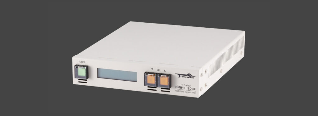
- Control functions such as channel switching and various information retrieval are available via LAN or from the front panel buttons / front LCD.
- Available information:
- BER
- C/N
- Reception level
- NET-ID
- TMCC
- Delay profile
- BER can be displayed by switching between:
- After Viterbi decoding
- After RS decoding
- With the included application, information can also be displayed via LAN.
- External Integration
- Upon request, the communication protocol can be disclosed to support control and information retrieval via TOP communication.
- Other Features
- Equipped with alarm contact output terminals
- IIP packet insertion enables output as a broadcast TS
- Supports simultaneous TS output via DVB-ASI (2 outputs) and DVB-SPI
- Can be configured to support Brazilian channels
Included Application
Example Use of DMB-2-ISDBT (1) — For TTL Backup
TTL (Transmitter to Transmitter Link) typically uses microwave links to transmit broadcast TS from one relay station to another. Traffic Sim proposes a TTL backup solution using the DMB-2-ISDBT.

Mechanism
The broadcast wave normally transmitted from the sending side is received by an antenna, demodulated by the DMB-2-ISDBT, and the resulting TS is directly input to the modulator on the retransmission side.
This configuration is possible because the DMB-2-ISDBT is capable of directly outputting broadcast TS.

Issues with Conventional Demodulators
In general, a TS obtained by receiving and demodulating a broadcast wave does not include hierarchical information or IIP, and therefore cannot be used directly as a “broadcast TS” input to a modulator.
For this reason, some demodulators that support broadcast TS output adopt a method of regenerating broadcast TS by internally remultiplexing (REMUX) the demodulated TS.
However, when such internally remultiplexing demodulators are used for TTL retransmission, there is an inherent risk.
The TS transmitted via broadcast waves is carefully multiplexed within the broadcast station’s MUX equipment, with precise control over packet intervals and audio/video timing. In demodulators that perform internal REMUX, this TS is recombined inside the device, which may not preserve the original high-quality TS generated at the broadcast station.
Features of DMB-2-ISDBT (Maintaining Original Quality)
Using a proprietary method, the DMB-2-ISDBT directly adds TMCC to the received TS, enabling it to reproduce the original broadcast TS almost exactly as it was.
Compared to conventional REMUX-type demodulators, this allows retransmission while maintaining the original quality.
Furthermore, at the retransmission site, modulation output is synchronized to a highly accurate reference clock obtained from GPS or similar sources. Therefore, the broadcast TS input to the modulator must also be synchronized to this reference clock.
The broadcast TS output by the DMB-2-ISDBT maintains the data rate of the input broadcast TS. Since the broadcast TS data rate is synchronized to the reference clock within the broadcasting station, the output TS of the DMB-2-ISDBT can be regarded as indirectly synchronized to the broadcaster’s reference clock.
As a result, the modulation clock at the retransmission point and the data rate of the DMB-2-ISDBT output TS become pseudo-synchronized, enabling stable retransmission over long periods.
Example Use of DMB-2-ISDBT (2) — As an SFN Checker
In areas where signals can be received from multiple antennas, the signal arriving from one antenna becomes the main signal, while the others are received as delayed waves. Terrestrial digital broadcasting uses an OFDM modulation scheme with a guard interval, allowing correct demodulation as long as delayed waves are within a certain range.
However, if the delayed waves exceed the allowable range of the guard interval, they become noise relative to the main signal and can degrade quality. Therefore, in SFN operation, it is necessary to pay close attention to synchronization among transmission sites (antennas).
Visualizing Delayed Waves and Noise, and Periodic Monitoring
Using the DMB-2-ISDBT SFN Checker application, you can confirm what kinds of delayed waves and noise are present relative to the main signal. In addition, by observing periodically, you can continuously monitor whether the delayed-wave conditions are fluctuating.

SFN Operation and Detecting Timing Offsets
In an SFN, a reference clock from GPS or similar sources is supplied to each antenna to synchronize time. Within the network_synchronization field contained in the signal’s IIP, there is SFN_synchronization_information. Based on this information, parameters such as the delay time at each transmission site are specified and adjusted so that problems do not occur even in areas where signals overlap.
Normally, if a peak within a certain range (the green area) shifts, it may indicate that the above parameters were changed on the transmission side. Another possibility is that one of the antennas in the reception area is no longer receiving the reference clock properly, causing synchronization to drift.
The SFN Checker monitors such timing shifts and notifies anomalies, helping with early detection and resolution of issues.

Specifications
| Product Type | ISDB-T Demodulator | |
|---|---|---|
| Product Name | TS CaPID DMB-2-ISDBT | |
| Model Number | DMB2-A2S1HR-ISDBT | |
| Input / Output | Input | RF ×1 (75Ω, F-type connector) |
| TS Output | DVB-ASI×2 DVB-SPI×1 | |
| Contact Output | D-Sub 9-pin (female) ×1
Photomos relay contact output | |
| Power | AC 100V–240V | |
| Apparent Power | 20VA | |
| Power Consumption | 12W | |
| Acceptable Reception Level | –67 to –28 dBm (93–465 MHz) | |
| Supported Standards | ISDB-T ISDB-Tb ISDB-Tsb | |
| Supported Frequency Range | Japan (ISDB-T) | 90–770 MHz VHF 1–12ch, UHF 13–62ch, CATV 13–62ch |
| Brazil (SBTVD) | 79–785 MHz VHF 7–13ch, UHF 14–66ch, CATV 5–99ch | |
Operating Temperature / Humidity | 5–40°C 30–80% RH (non-condensing) | |
| Return Loss | 90~770MHz:6dB | |
| Dimensions (W × H × D) | EIA 19-inch rack, 1U half size | |
| Weight | Approx. 1.3 kg | |
| Accessories | Power cable (AC100V) | |
| Options | Rack-mount support angle U-1 (mount one unit in 1U) | |
| Related Products | TS Monitoring System (AlertMagic) TS Simultaneous Recording System (TSR-1000) Descrambler (DSCR-1) | |